I build models across scales, from atoms to full parts: heat transfer in the melt pool, residual stress and distortion in a build, the mechanical response of printed structures under load, and the thermodynamics of the alloy itself.
Most of my finite element work is in Abaqus, with my own subroutines where the standard tools fall short. I check each model against printed parts, micrographs, thermocouples or mechanical tests.
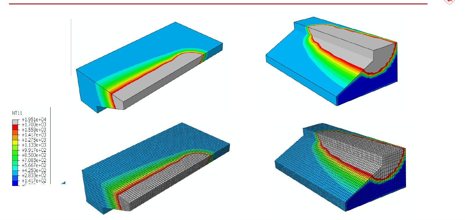
Thermal model of a laser track on bulk metal and the powder beneath an overhang.
What I simulate
Seven kinds of model, chosen to fit the question.
Thermal and heat transfer
Moving laser and electron-beam heat sources, melt-pool size and shape, heat build-up in overhangs, and the effect of powder, preheat and scan strategy.
Abaqus, DFLUX subroutines
Thermo-mechanical
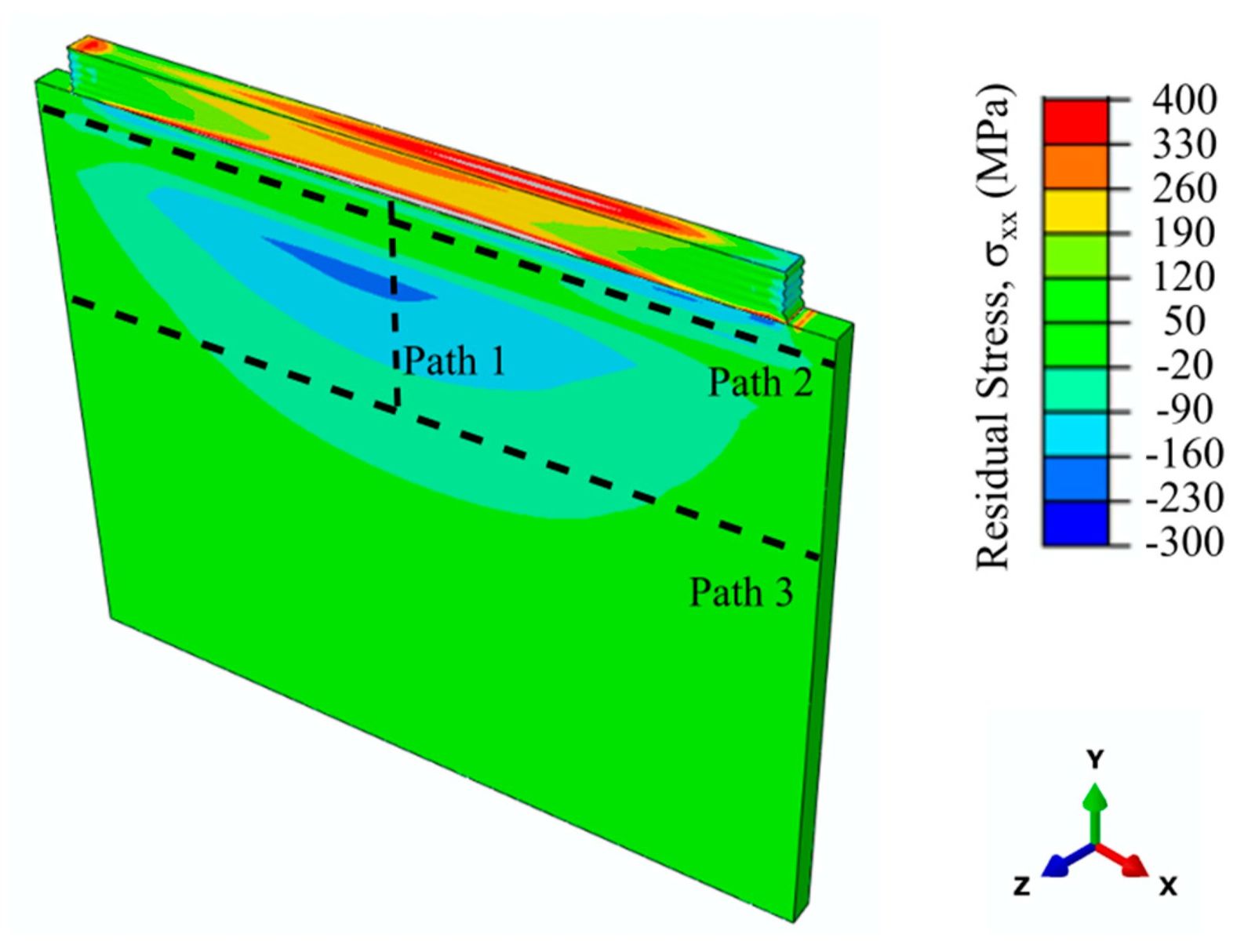
Coupled temperature and stress models that predict residual stress and distortion, from a single laser shot to a wire-fed electron beam deposit validated within 3.7%.
Abaqus
Mechanical and structural
Tensile and fatigue behaviour of printed microstruts, with models built from CT scans of real surfaces: stress concentration, plastic strain, necking and failure location.
Abaqus, ANSYS
Melt-pool fluid flow
Finite volume models of the melt pool with Marangoni flow, recoil pressure and surface tension, used alongside FEM for multi-scale process modelling.
FVM
Atomistic
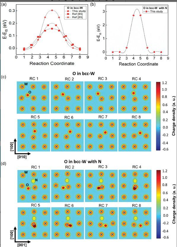
Density functional theory for nitrogen and oxygen diffusion in tungsten, which explained how to print it without cracks.
Quantum ESPRESSO
Thermodynamics
CALPHAD calculations of phases and solidification paths for alloy and heat-treatment design.
FactSage
Build-scale and data models
Part-scale distortion prediction before printing, plus regression and decision-tree models that link laser parameters to density and surface.
Netfabb, Python, MATLAB, R
Simulation in motion
Short videos from my process models.
Heat building up in an overhang
My Abaqus thermal model of a laser passing over an IN625 overhang at 45°, 30°, 20° and 10° (100 W, 600 K preheat). The flatter the overhang, the less powder-free metal there is to carry heat away, and the deeper the melt pool grows: from about 200 µm at 45° to over 1.1 mm at 10°. This is why low overhangs fail, and what my support-free strategy is designed to stop.
45° overhang30° overhang20° overhang10° overhang
Simulation examples
Models I built in Abaqus to understand what happens inside the build, each checked against real parts.
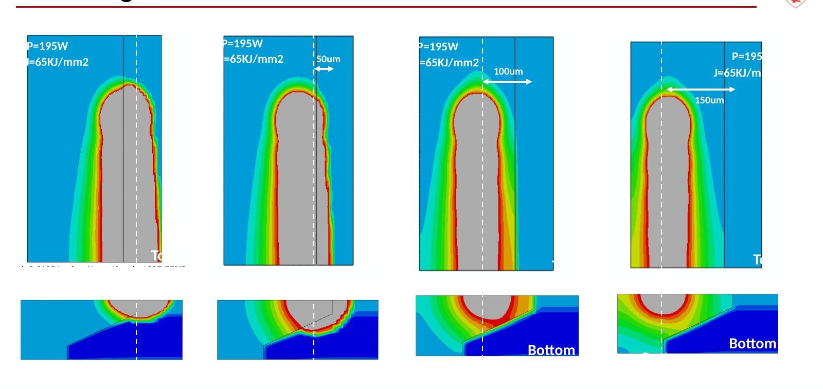
Melt pool size at the overhang tip
Where the laser runs relative to the overhang edge decides whether the part survives. I modelled a 195 W track on SS316L with the laser placed at the edge and then offset 50, 100 and 150 µm inward. At the edge, much of the melt pool sinks into loose powder, which conducts heat poorly, so the pool grows deep and dross forms underneath. Moving the track inward keeps more of the pool on solid metal and shrinks it. Results like this shaped my support-free overhang strategy.
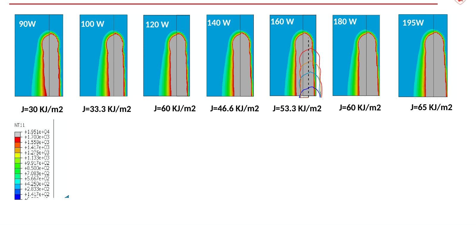
Laser power on a 25° overhang
A single-layer Abaqus thermal model with my own moving Gaussian heat source (a DFLUX subroutine), run over a matrix of seven laser powers from 90 W to 195 W and three overhang angles: 25°, 45° and 90°. The model separates the bulk metal from the powder region underneath. On the 25° overhang the melt pool reaches further into the powder with every step in energy density, from 30 to 65 kJ/m². This tells you how far power can be pushed before the overhang starts to sag.
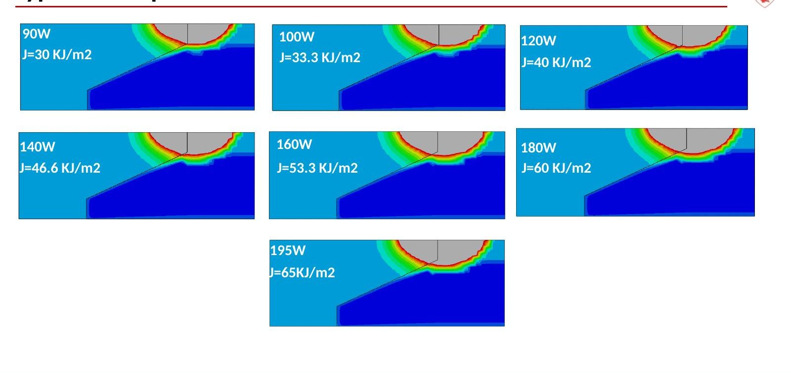
The melt pool at the solid–powder interface
A close look at the melt pool where solid metal meets powder, for the same seven powers. Low power gives a shallow, conduction-mode pool that sits mostly on solid metal. High power gives a deeper pool that grows asymmetrically into the powder side. The shape of that pool controls cooling direction, and so the grain texture that forms in the overhang. Keeping the pool shape consistent along the overhang is the key to a uniform texture.
Effect of the powder layer
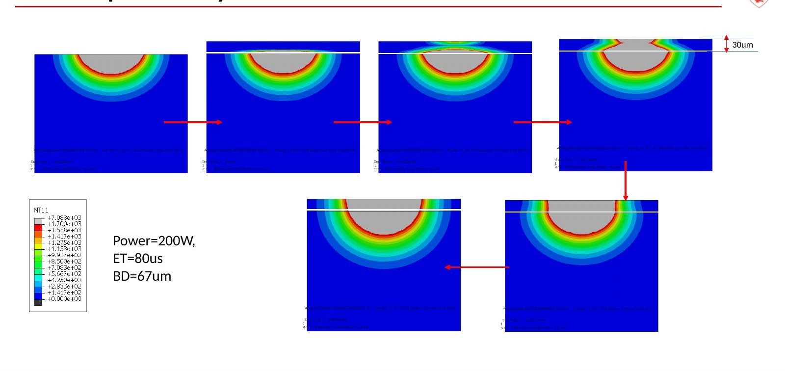
A 200 W laser modelled through successive 30 µm powder layers. As each layer is added, the melt pool must first melt the loose powder before it fuses with the solid below, so penetration into the previous layer drops. This explains why the first layers over an overhang behave differently from the bulk, and why my strategy uses a slightly higher energy density on skipped regions to keep them bonded to the layer underneath.
Tensile behaviour of rough microstruts
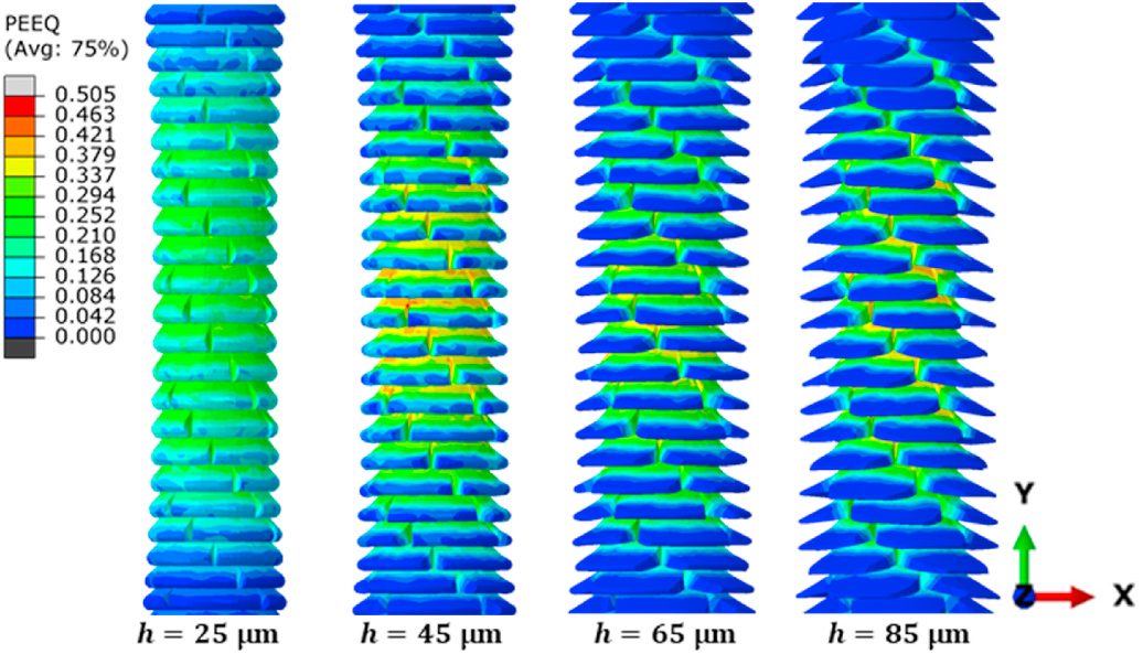
With Abhi Ghosh, I built 3D finite element models of 250 µm SS316L struts from tomography of real LPBF surfaces, then added uniform notch-like features 25 to 85 µm tall. Under tension, stress concentrates at the notch roots. That raises the ultimate tensile strength from 533 MPa for a smooth strut to as much as 760 MPa, but it cuts uniform elongation from about 0.52 to 0.36–0.38. In short, as-built roughness makes thin lattice struts stronger but less ductile.
Where rough struts fail
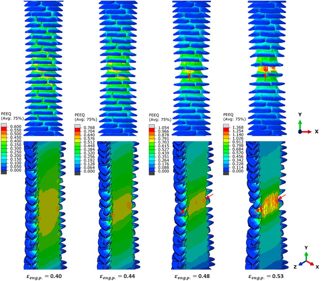
The same models, followed past the ultimate tensile strength. Plastic strain gathers at the roots of the surface features, and the point of highest triaxiality moves to those notches. That is where the final failure starts, which shows why polishing or designing out roughness matters for lattice parts that carry load. Published in Materials Science and Engineering A, 2022.
How I built up the LPBF thermal model at McGill, one step at a time (2018–2019).
I started with a single laser shot on SS316L (120 W, 200 µs, 120 µm beam) and compared heat-source shapes: Gaussian surface, cylindrical, conical and ellipsoidal. Raising the Gaussian order from n = 1 to n = 2 lifted the peak temperature from about 5,500 K to 8,900 K, so the heat-source choice matters as much as the laser settings. I then modelled powder as its own material, with effective density, specific heat and conductivity, and moved on to a scanned line and to overlapping spots, where the point distance follows pd = r(2 − overlap).
Coupled temperature and stress model of a single laser shot. Left: the temperature field and melt pool. Right: von Mises stress as the pool forms. The plots below track heat flux, temperature across the surface and into the depth, and stress on the top surface, which peaks at about 500 MPa on either side of the melt pool.
Single laser shot: melt pool and surface deformation (120 W, 200 µs).Scanned line, side view (sped up 4×).Scanned line, top view (sped up 4×).Overlapping tracks in 3D: temperature field.Overlapping tracks: heat-flux vectors near the laser.
Case study: the right power for low-angle prints
From my modelling work at McGill, 2018–2019.
Step 1: the melt pool grows toward the tip
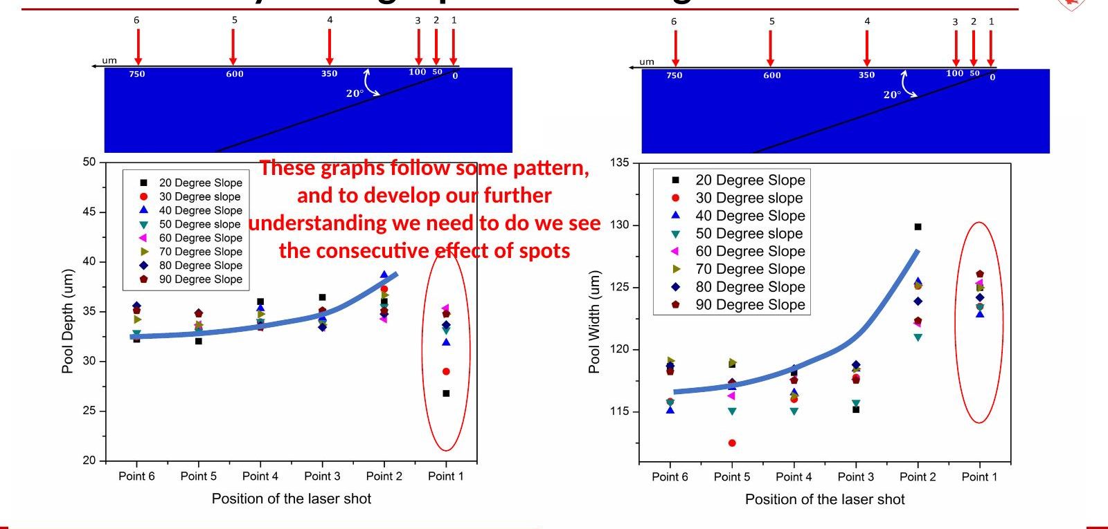
I placed single laser shots (100 W, 400 µs, 120 µm beam, 47 µm point distance) along slopes from 20° to 90°. The thermal model was validated against measured melt pools, 152 ± 8 µm wide and 34 ± 2 µm deep. Away from the edge, pool depth and width stay flat. Over the last few shots before the overhang tip they climb sharply, most of all on shallow slopes, because there is less solid metal underneath to take the heat away.
Step 2: stable, transition and unstable zones
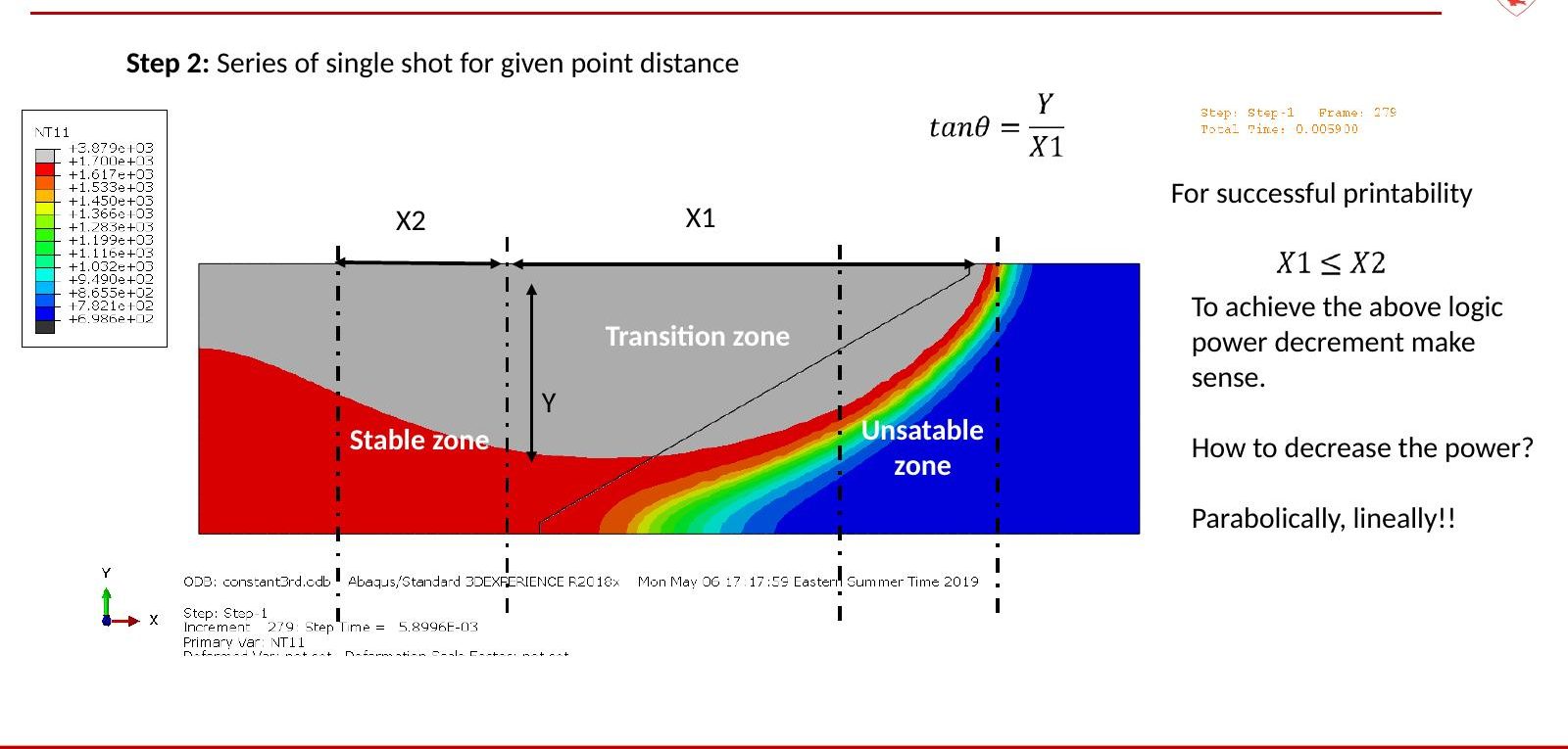
Running a series of shots showed three zones: stable over solid metal, a transition zone, and an unstable zone at the tip where the pool sinks into powder. For a slope θ, a layer prints cleanly when the stable length X1 stays within X2, with tan θ = Y / X1. That gave a simple rule: keep the power constant in the stable zone and lower it as the laser approaches the tip.
Step 3: shaping the power near the edge
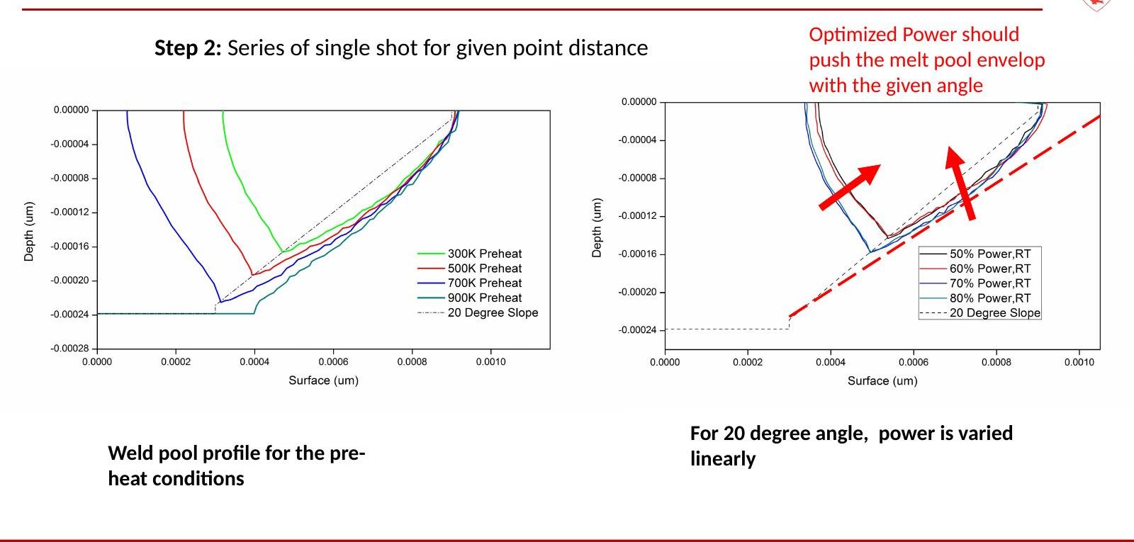
On a 20° slope I compared preheat temperatures and reduced power to 50–80% near the edge. Preheat made the pool deeper. Reducing the power pulled the melt pool envelope back toward the line of the overhang angle, which is what you want. Changing parameters near the edge, rather than adding supports, became the starting point for my later support-free work.
More models
Other simulation work, each described in full on the Projects page.
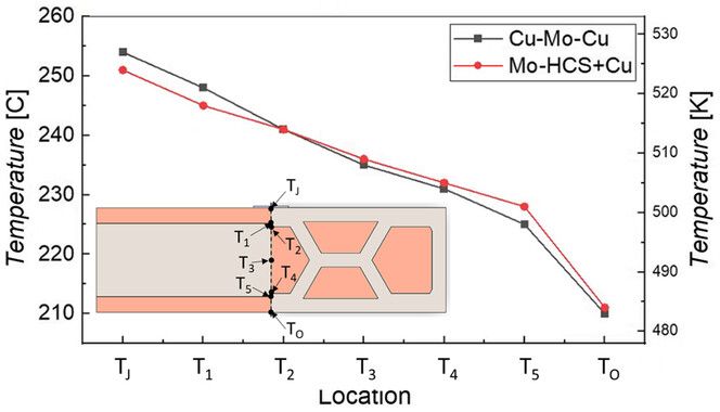
Thermo-mechanical model of wire-fed electron beam AM: temperature, distortion and residual stress in Ti-6Al-4V.Thermal performance of a Mo, Nb and TZM exoskeleton heat sink with copper infiltration.Atomistic (DFT) calculations behind crack-free laser-melted tungsten in argon and nitrogen.
Need a model for your build?
I also teach simulation for metal AM, from FEM basics to thermo-mechanical models of real parts.