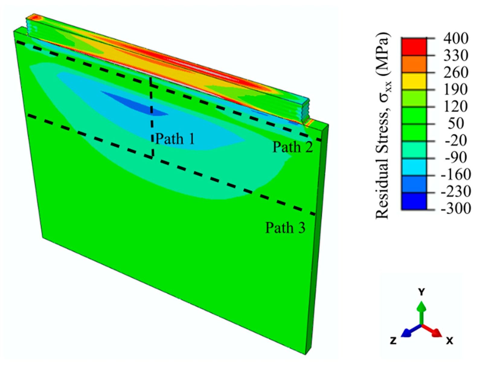
I have built thermo-mechanical models of additive processes in Abaqus for wire-fed electron beam deposition, for laser powder bed fusion overhangs, and for heat accumulation in thin features. One of them, a model of electron beam additive manufacturing of Ti-6Al-4V, matched measured temperatures with an average error of 3.7%, residual stress within about 100 MPa and distortion within 0.05 mm. That took a long time, and most of the time went into problems that nobody writes about in the paper.
This is a practical article about those problems. It is for students and engineers starting their first process model.
Decide what question the model answers
The biggest mistake I see is building a model before deciding what it is for. A model to compare two scan strategies needs different detail from one to predict final distortion, and both differ from a model of the melt pool.
Write the question down. “Will the plate distort more than 0.5 mm with strategy A or B?” is a good question. “Simulate the build” is not. The question decides the scale, the mesh, the physics and, above all, what you will measure to validate it.
Sequential or coupled
For most additive and welding problems, a sequentially coupled analysis works well: first a heat transfer analysis to get the temperature history, then a stress analysis that reads those temperatures. It is faster and easier to debug than a fully coupled analysis, and it is accurate when deformation does not significantly change the heat flow.
Fully coupled temperature-displacement analysis is worth it when large distortion changes the contact or the geometry during the process. Start sequential. Move to coupled only when you have evidence you need it.
Adding material: element activation
Additive processes add material over time, so the model has to as well. The usual approaches in Abaqus are:
- Model change (removing and reactivating element sets), which is simple but awkward for many small increments.
- “Quiet” elements, present from the start with very low properties, which avoids activation but can cause numerical problems and artificial heat flow.
- The AM modules (progressive element activation driven by an event series), which link activation and heat input to a toolpath. These are the most practical route for detailed AM simulation today.
Whichever you use, check what the newly activated elements are doing at the moment they appear: their temperature, their strain state and whether they inherit stress they should not have.
The heat source
For welding and DED, a Goldak double-ellipsoid heat source is a common starting point. For LPBF at part scale, you cannot follow the laser track by track, so layers or groups of layers are heated at once with a lumped heat input. Both need calibration.
The heat source parameters are rarely known in advance. Absorptivity in particular depends on the material, the powder and the process conditions. Calibrate against a measured melt pool cross-section or thermocouple data, then keep the calibration fixed when you compare cases. A model calibrated separately for every case proves nothing.
Mesh and time steps
Thermal gradients near the heat source are extremely steep. Too coarse a mesh smears them out and underpredicts stress; too fine a mesh makes the run impossibly long. Practical rules:
- Refine where the heat goes and where you want answers; coarsen away from them.
- Use a mesh that follows the layer or bead geometry so activation boundaries are clean.
- Do a mesh convergence study on a small version of the problem. It is tedious and it is not optional.
- Watch the time increment. Abaqus’s automatic incrementation will take small steps during heating and large ones during cooling. Limit the maximum temperature change per increment so the solution does not jump over important events.
Linear elements with full integration can lock under thermal strain; check the element formulation for the stress step.
Material data: the weakest link
Most models fail here, quietly. You need conductivity, specific heat, density, thermal expansion, elastic modulus, yield stress and hardening, all as functions of temperature, up to and beyond melting. Published data is often incomplete above about 1000 °C, and many datasets come from wrought material, not AM material.
Things that matter more than people expect:
- Latent heat of melting and solidification, which affects the temperature history.
- Annealing behaviour. Above a certain temperature, accumulated plastic strain should be reset, or the model builds up unrealistic hardening and stress. Abaqus provides an annealing temperature option for this.
- Powder properties for the surrounding bed, with much lower conductivity than the solid.
- Phase transformations, for alloys like Ti-6Al-4V and steels, where volume changes contribute to stress.
When data is missing, say so, run a sensitivity study, and find out which properties actually change the answer.
Boundary conditions
Convection and radiation from free surfaces, conduction into the build plate, the clamping of the substrate and the plate’s own temperature all matter. Radiation is often significant at high temperatures and easy to forget. Clamping conditions decide much of the final distortion, and should be modelled as they are in the real process, including when the clamps are released.
Validation is the model
A process model without validation is a drawing. I would validate on at least two of:
- Temperature, using thermocouples at known locations or infrared measurements with calibrated emissivity.
- Distortion, measured by CMM or 3D scanning before and after release.
- Residual stress, measured by X-ray diffraction, hole drilling or the contour method, with awareness of each method’s depth and uncertainty.
- Melt pool size, from sectioned and etched samples.
Compare like with like: the same location, the same time, the same direction of stress. And report the disagreements honestly. The places where a model disagrees with measurement are where you learn something.
Run times and practical tips
- Start with a small, simple model and add complexity one feature at a time.
- Use symmetry where the geometry and the process allow it.
- Save restart files during long runs.
- Script the model in Python. You will rebuild it more times than you expect, and scripting makes parameter studies possible.
- Keep a log of every assumption. Six months later, you will not remember why the convection coefficient is 15.
A good process model is not the one with the most detail. It is the one that answers its question with known uncertainty and has been checked against reality. Everything in this article is in service of that.
Further reading
- Sikan, F., Wanjara, P., Gholipour, J., Kumar, A. and Brochu, M. (2021). Thermo-mechanical modeling of wire-fed electron beam additive manufacturing. Materials 14(4). doi:10.3390/ma14040911
- Goldak, J., Chakravarti, A. and Bibby, M. (1984). A new finite element model for welding heat sources. Metallurgical Transactions B 15.
- Kumar, A., Brochu, M. and Atabay, S. (2025). Understanding residual stresses in the field of additive manufacturing. ASM Handbook, Volume 25A.