Most conversations about laser powder bed fusion are about the process: laser power, scan speed, hatch spacing, supports, orientation, build time. Those are the knobs we can turn, so it is natural that we talk about them.
But every one of those knobs acts on metal. The laser does not make a part directly. It makes a melt pool, the melt pool solidifies, and the solidified metal is reheated dozens of times as new layers are added. What comes out is a microstructure, and the microstructure decides the properties. I trained as a metallurgist, and the more parts I print the more convinced I am that physical metallurgy is the chapter most LPBF stories skip.
A printed alloy is not the wrought alloy
The same IN625 composition printed by LPBF and made by forging are different materials. Cooling rates in an LPBF melt pool are orders of magnitude higher than in casting or welding. The result is a very fine cellular or cellular-dendritic solidification structure, with alloying elements such as niobium and molybdenum pushed to the cell boundaries. Grains grow epitaxially from the layer below and tend to become columnar along the build direction, often with a strong texture.
In the support-free IN625 impellers I printed, the cells in the bulk were about 0.7 µm across and the grains grew columnar along the build direction with an aspect ratio of about 3.5. Primary dendrite arm spacing was larger at 60 µm layers than at 30 µm layers, because a bigger melt pool cools more slowly. That is one small example of a process choice showing up directly in the microstructure.
This matters because datasheets, heat-treatment schedules and design allowables are usually written for wrought or cast material. They are a starting point for printed parts, not an answer.
Geometry changes the metallurgy
One of the most interesting results of my doctorate was how much the microstructure changes inside a single part. In a zero-degree internal overhang, the downskin sits on loose powder and cools far more slowly than the bulk. The cells at the downskin were about 4.7 µm, nearly seven times coarser than in the bulk.
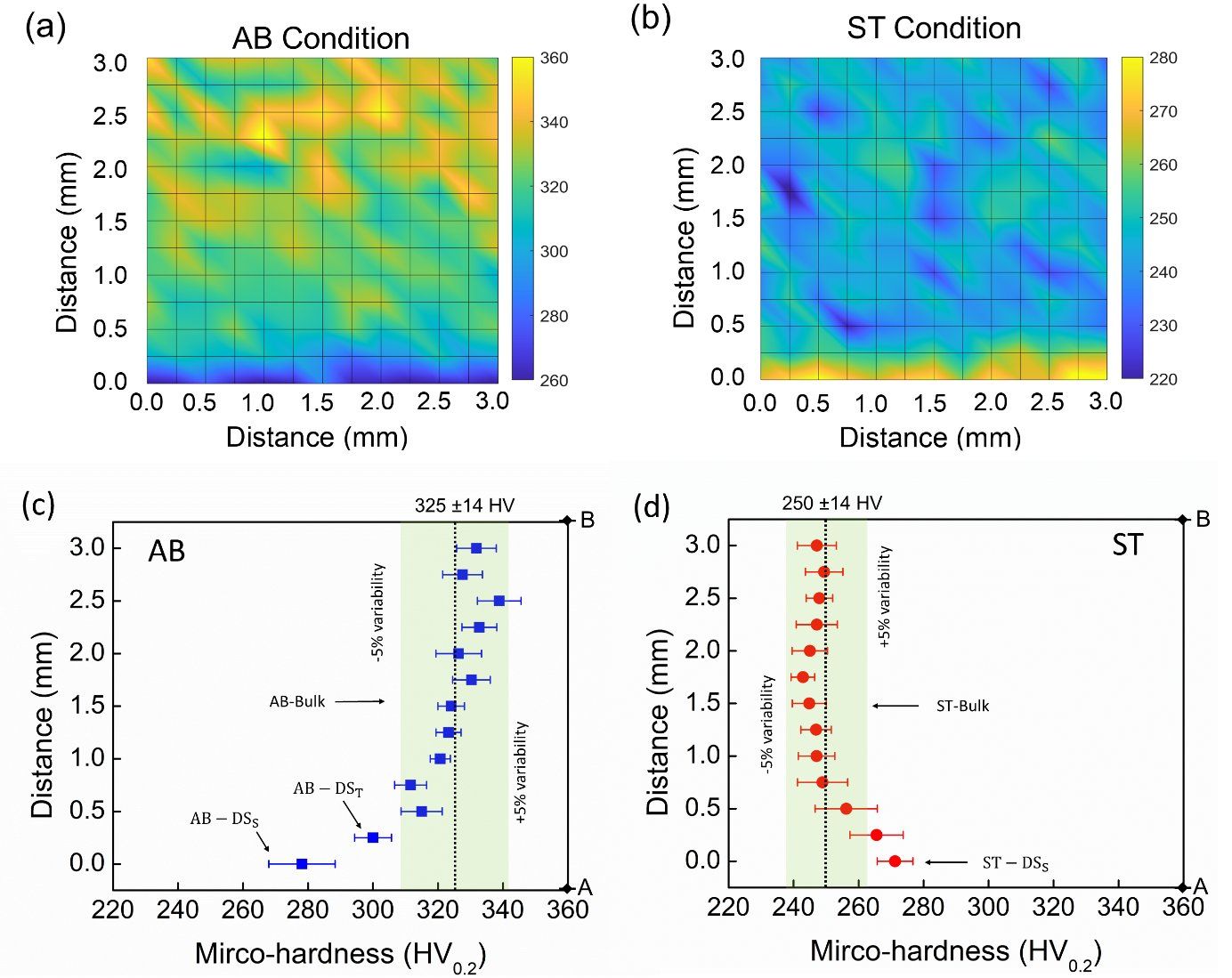
The dislocation content changed too. Using EBSD with kernel average misorientation and geometrically necessary dislocation maps, we measured about 1.3 × 10¹⁴ m⁻² in the bulk and about 0.7 × 10¹⁴ m⁻² at the downskin. Hardness followed: about 322 HV in the bulk and 278 HV at the downskin.
So a support-free part is not one material. It is a graded material, and the grading follows the geometry. A designer who places a high-stress feature on a downskin surface is placing it on a different microstructure, with a different surface.
Heat treatment does not simply reset the part
The usual instinct is to heat-treat a printed part and assume that the as-built differences disappear. Our solution-treatment results showed that is too simple.
After solution treatment, the bulk recrystallized and its grains grew. Its hardness dropped from about 322 to 252 HV, as expected when cells, segregation and dislocations are swept away. The downskin behaved differently. With less stored energy from dislocations, it recrystallized only within about 130 µm of the surface, and its hardness barely changed, about 278 HV before and 271 HV after.
The hardness gradient across the part did not disappear. It reversed. The downskin ended up harder than the bulk.
Explaining it with strengthening mechanisms
Physical metallurgy gives a way to explain this rather than just report it. A metal’s flow stress can be broken into contributions: the lattice itself, solid-solution strengthening from alloying elements, grain-boundary strengthening, cell-boundary strengthening in as-built LPBF material, dislocation strengthening, and Orowan strengthening from fine particles.
When we did that accounting for the overhang, the picture became clear. In the as-built bulk, cell boundaries and dislocations carried much of the strength. Solution treatment removed most of that, so hardness fell. At the downskin, grain size and dislocation content stayed similar, and more carbides formed during treatment. The loss of cell-boundary strengthening was roughly balanced by a gain in Orowan dispersion strengthening, so hardness stayed about the same.
That kind of explanation is what lets you predict the next part instead of testing every one.
Heat treatment schedules need rethinking
The same thinking applies to standard heat treatments. Wrought IN625 practice stress-relieves at temperatures that, for LPBF material with its segregated cell boundaries, can promote unwanted secondary phases. In my industrial work on an IN625 swirler, I set the stress relief at a lower temperature for that reason. It is a small decision with a metallurgical reason behind it, and that reason should be written down.
Refractory metals make the point even more strongly
Tungsten is a good reminder that metallurgy can decide whether printing works at all. LPBF tungsten tends to crack because oxygen collects at grain boundaries and weakens them. In work I contributed to, building under nitrogen instead of argon gave crack-free parts, and my density functional theory calculations showed that dissolved nitrogen hinders the diffusion of oxygen. The fix came from understanding atoms at grain boundaries, not from another parameter sweep.
What I would like the field to do
I would like every serious LPBF development program to include a metallurgist from the start, not only at failure analysis. In practice that means:
- Characterize the as-built microstructure in the regions that matter, including downskins, thin walls and overhangs, not only a convenient cube.
- Measure stored energy with EBSD-based methods, because it predicts the heat-treatment response.
- Design heat treatments for the printed material, not copy wrought schedules, and check for secondary phases.
- Explain properties with mechanisms, so that results transfer to the next geometry and the next machine.
- Treat geometry as a metallurgical variable, because overhangs, thin sections and heat accumulation all change the local structure.
Process parameters tell you what you did to the metal. Physical metallurgy tells you what the metal did in return. A good LPBF engineer needs both.
Further reading
- Kumar, A. and Shandiz, M.A. (2025). Solution heat treatment of support-free IN625 overhang sections fabricated via laser powder bed fusion. Progress in Additive Manufacturing 10, 7085–7099. doi:10.1007/s40964-025-01029-0
- Kumar, A., Shandiz, M.A., Sikan, F. and Brochu, M. (2023). Microstructural and mechanical properties of an internal support-free IN625 closed impeller manufactured via L-PBF. Materials Science and Engineering A 874. doi:10.1016/j.msea.2023.145080
- Ramakrishnan, T., Kumar, A. et al. (2023). Crack-free tungsten fabricated via laser powder bed fusion additive manufacturing. Advanced Functional Materials. doi:10.1002/adfm.202309304
- Porter, D.A., Easterling, K.E. and Sherif, M.Y. Phase Transformations in Metals and Alloys. CRC Press.